Brine Recovery
Recovery Technology
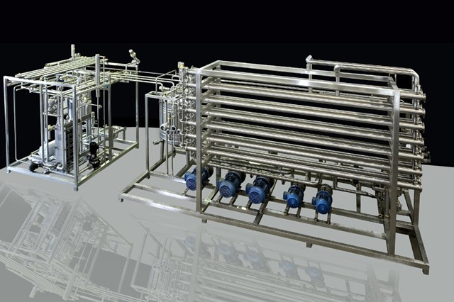
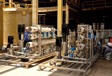
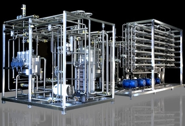
The Brine Recovery System is an advanced industrial solution designed to recover and reuse caustic brine from sugar refinery processes. By integrating membrane filtration and ion exchange technologies, the system significantly reduces effluent discharge while improving operational efficiency and sustainability.
This system ensures optimal resource utilization by recovering valuable chemicals and minimizing environmental impact, making it an essential component for modern sugar, ethanol, and chemical processing industries.
System Overview
In sugar refineries, ion exchange resins are widely used for decolorization of sugar syrup. During regeneration, large volumes of colored spent caustic brine are generated, which traditionally require disposal and treatment.
The Brine Recovery System eliminates this challenge by recovering reusable brine through advanced membrane separation. This reduces chemical consumption, lowers operational costs, and ensures compliance with environmental norms.
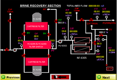
Process Flow & Operation
- Collection of spent brine in storage tanks
- Pre-filtration using bag filters and sand filters
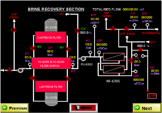
- Fine filtration through cartridge filters
- High-pressure pumping into membrane modules
- Separation into permeate (clean brine) and retentate
- Recycling of permeate back into the system
- Disposal or treatment of concentrated reject
- Automatic cleaning using CIP system
Technical Specifications
| Flow Rate | 4.75 – 7.0 Cum/Hr |
| Recovery Rate | 75% – 95% |
| Operating pH | Up to 13 |
| Temperature | Up to 70°C |
| Automation | Fully Automatic PLC + HMI |
| Material of Construction | SS316 / FRP |
Key Advantages
- Eliminates need for acid neutralization
- Significant reduction in chemical consumption
- Lower effluent treatment cost
- High recovery efficiency up to 95%
- Improved plant sustainability
- Fully automated and easy to operate
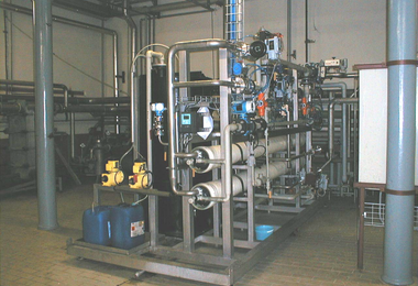
- Compact and modular system design
Working Principle
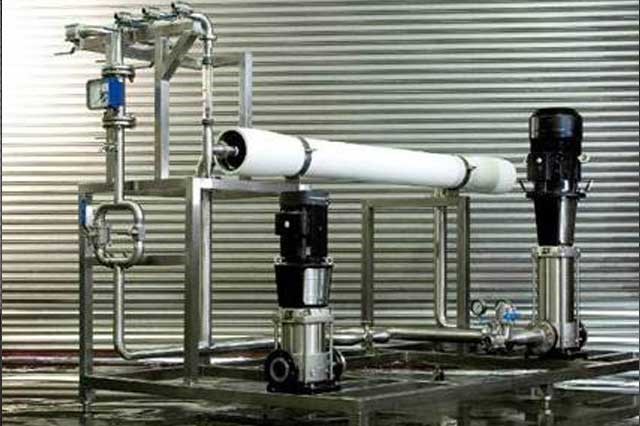
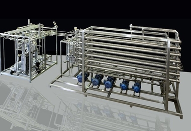
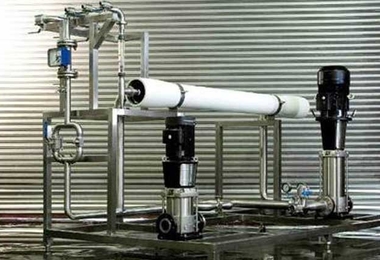
The system operates on membrane separation technology, where high-pressure pumps force the brine solution through specialized membranes. These membranes allow clean brine to pass while rejecting impurities, color compounds, and dissolved solids.
The recovered permeate is reused in the process, while the retentate is either treated further or safely discharged, ensuring minimal environmental impact.
System Components
- Feed Tank & Storage System
- Bag Filter & Sand Filter
- Cartridge Filtration Units
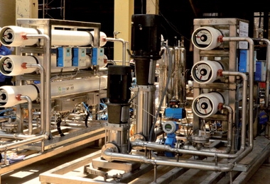
- High Pressure Pump with VFD
- Membrane Modules
- PLC Control Panel with HMI
- CIP Cleaning System
System Performance
The system is capable of handling a wide range of flow rates and operating conditions. With high recovery efficiency and stable operation at elevated pH levels, it ensures consistent performance in demanding industrial environments.
Its modular design allows easy expansion, making it suitable for both small-scale and large-scale industrial applications.
Applications
- Sugar Refineries
- Starch & Glucose Plants
- Ethanol & Distillery Units
- Food Processing Industry
- Chemical Processing Plants
- Water Treatment Systems
Business Benefits
- Reduction in operational costs
- Improved resource efficiency
- Quick return on investment (ROI)
- Compliance with environmental regulations
- Enhanced production efficiency
Need a Customized Solution?
Our team specializes in designing and delivering customized brine recovery solutions tailored to your plant capacity and process requirements. Contact us today to upgrade your system with advanced automation and sustainable technology.
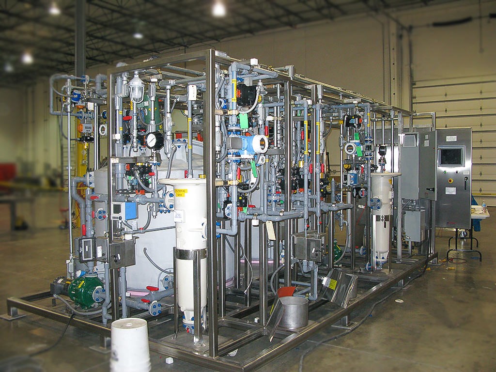
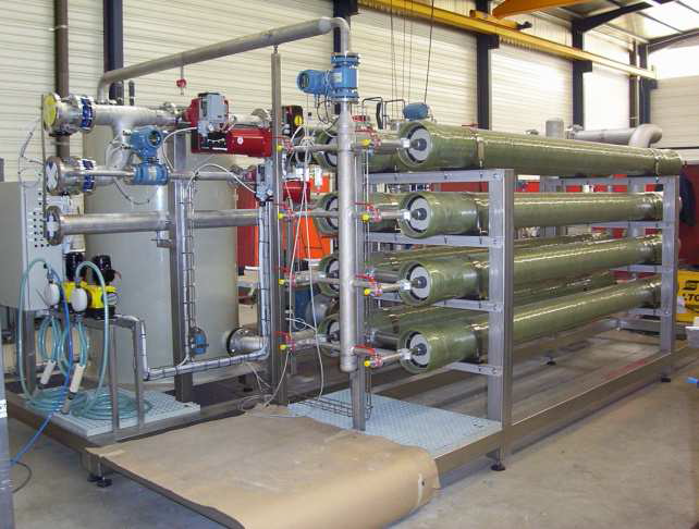
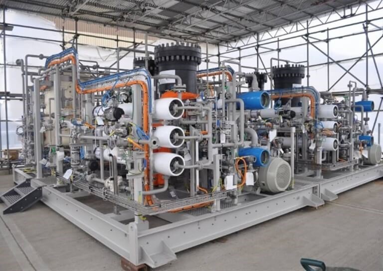
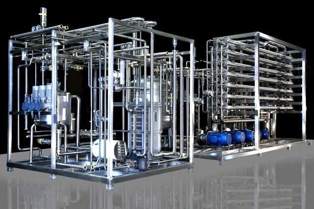
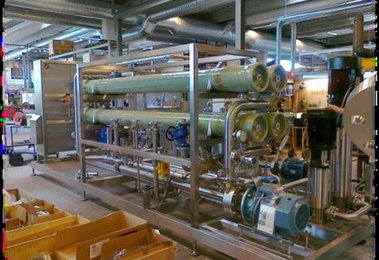
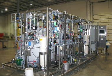
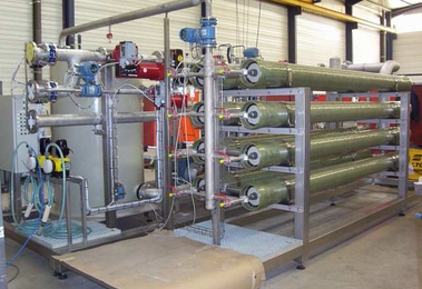
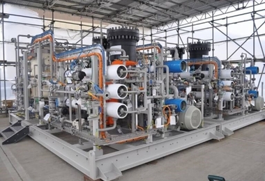
Brine Recovery Gallery
-
 BRINE1
 -
BRINE1
-
 BRINE2
 -
 BRINE3
 -
 BRINE4
 -
 BRINE5
 -
 BRINE6
 -
 BRINE7
 -
 BRINE8
 -
 BRINE9
 -
 BRINE11
 -
 BRINE12
 -
 BRINE14